Arduino 47mA
Lm324 (Quad Op-amp) 1.5mA
Lm35 (Thermistor) 15mA
24L256 (EEPROM) 33mA
Mx210A (accelerometer) 3mA
MPX100 (barometer) 10mA
TOTAL ~ 110mA
The circuit design is as follows and the code remains the same as it was in the last post.

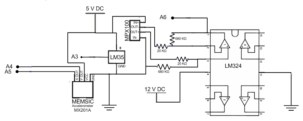
Note: there is supposed to be a logic switch on pin 14 and pin 15 of the arduino which tell the arduino whether to begin writing data or to read data (this process is in the code)
Superb and such a nice printed circuit board layout design work. i will bookmark this pot post for my future help.
ReplyDeletePrinted Circuit Board