Thursday, 27 October 2011
Future Plans
I am going to start work on a program that will log data from the analog inputs on the Atmegea 328. This will be used to log the data from a thermistor and a pressure meter that will be on board the flights. We want to be able to store this data on the Arduino, then retrieve after the flight. I will start by attempting to store data from 3 different analog voltages, then retrieve the data afterwords.
Wednesday, 26 October 2011
Exploder Circuit
I am creating a circuit and program to receive a signal from a switch, wait a certain amount of time, then send a voltage out. This will be used to explode a balloon after some time to test the parachute. The signal will leave the Atmega 328 and go though a buffer operational amplifier, and into a relay which is connected to a solar igniter. The buffer is to separate the Atmega from relay and the solar igniter. The chip will not supply enough current to ignite the igniter, so a relay must be used. The relay will supply current required to the solar igniter that will be attached to the balloon. Originally,a transistor was going to be used, but it leaked current and led to our igniter bursting before it was supposed to. The circuit was modified to contain a mechanical relay which worked, but the current draw through the mechanical relay was about 80 mA, which is high enough for concern (considering this is to be supplied by batteries while in flight). The final version (posted below), uses a solid state relay, which does not have current leakage problems and only draws 9 mA of current.
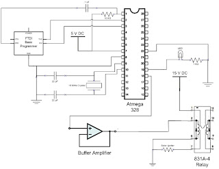

This circuit has been tested with an LED and a solar igniter at the output of the relay and works with both. The code used for the Atmega 328 is posted below.
/*
Balloon Exploder
Standby: Repeatedly blinks an LED
Recieves voltage at input, turns off standby
Waits 5 seconds, then sends a HIGH out to 12 and 13(LED)
*/
void setup() {
// initialize the digital pin as an output.
// Pin 13 has an LED connected
pinMode(13, OUTPUT); //pin 13 is set to an output
pinMode(8, INPUT); //pin 8 is set to an input
pinMode(12, OUTPUT); //pin 12 is set to output
digitalWrite(12,LOW); //pin 12 is initialized as low
}
void loop(){
while(digitalRead(8)==LOW){ // while loop reads pin 8 and will stay in loop until pin 8 recieves 5 volts
digitalWrite(13, HIGH); //writes pin 13 to 5 volts
delay(1000); //waits a second
digitalWrite(13, LOW); //writes pin 13 to 0 volts
delay(1000); //watis a seconds
}
delay(5000); // delays 5 seconds
digitalWrite(13, HIGH); //sets pin 13 to 5 volts
digitalWrite(12, HIGH); //sets pin 12 to 5 volts for transistor
while(1==1); //stays in this state until reset
}
Sunday, 23 October 2011
Schematic for the Blink Program for the Atmega 328
This is the schematic I used to operate the Atmega328 running programs written with the Arduino IDE. The FTDI Basic programmer plugs into the computer via usb cable. I first programmed the chip with the simple blink program.
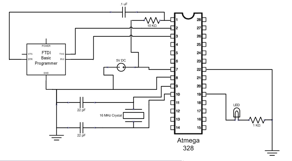
I used the code from the following link http://www.arduino.cc/en/Tutorial/Blink .
The next goal will be to modify the circuit and the programming to receive a digital input, wait a certain amount of time, then send 5 volts to an output. This will be used to pop the balloon when testing the parachute.
Subscribe to:
Posts (Atom)