The current draw was measured from the baloon exploder microchip, the gps, and, the buffer op amp, and the data aquisition arduino. The baloon exploder microchip draws about 22 mA while counting, the buffer draws 36 mA (used an lf411 to estimate, but this is a +/- 15V op-amp which we will be replacing with a one sided 12V one that will draw less), the data aquisition microchip draws 25 mA, and the gps draws 45 mA. We are missing current draw from a few 12V regulators, but these aren't in yet, but the draw should be rather low. The current draw from the actual fuze itself is negligible because it will only draw current for less than a second. This gave us an estimated total of 128 mA draw from the entire circuit.
We are planning to use two 9V batteries in series to make 18V which we can regulate down. These batteries have a capacity of 500mAh, giving us an estimated 3.9 hours. These batteries have an operating range of -20°C to 54°C. This should be more than enough for the test flight.
Wednesday, 9 November 2011

Friday, 4 November 2011
EEPROM MEMORY STORAGE
I have been working on a program that will take data, and store it. Regularly when values are taken from a microchip, the data is stored into SRAM, which is cleared when the power is reset. For our balloon we want to be able to measure voltages from thermistors, pressure sensors and possibly other devices, and we don't want to lose this data when the power is shut off. So this data must be stored to either the EEPROM memory or the Atmega's flash memory. The difference between the two is that data going into EEPROM can only be stored byte by byte, and must be addressed where it is going, where data in flash memory can be stored in tables and arrays and are just stored "somewhere". After struggling with storing and retrieving data from flash memory, I decided to try using the EEPROM, even though we will likely have to use flash memory due to the lack of space in the Atmega's EEPROM.
***UPDATE*** The EEPROM memory will have to be used because only compiled information can be stored in the flash memory. Anything being declared after complile stages cannot be stored in the flash memory. We have placed and order for a seperate EEPROM memory chip that has 128 kB of memory, which will be more than enough for storing the flight data.
Below, is the code I successfully wrote for this process. I will be attempting to learn and figure out how to properly store and retrieve data into the flash memory.
/*
Analog Reader
Standby: Repeatedly blinks an LED
Recieves voltage at input 8, turns off standby
Repeatedly reads Voltages from analog pin 0, stores them in EEPROM memory.
Once switch is turned, stops storing and goes into stanby 2 waiting for an input a pin9
Once this is turned, it will read values either until it has read them all, or pin9 is turned off
*/
#include <EEPROM.h>
void setup() {
pinMode(8, INPUT); //pin 8 is set to an input
pinMode(13, OUTPUT); //pin 12 is set to output
pinMode(9,INPUT); //pin 9 is set to an input
Serial.begin(9600); // baud rate for the chip is set to 9600
}
void loop(){
int sensor0 = 0; //int to store value read from A0
while(digitalRead(8)==LOW){ // while loop reads pin 8 and will stay in loop until pin 8 recieves 5 volts
digitalWrite(13, HIGH); //writes pin 13 to 5 volts
delay(1000); //waits a second
digitalWrite(13, LOW); //writes pin 13 to 0 volts
delay(1000); //watis a seconds
}
digitalWrite(13,HIGH);
int k=0;
while(digitalRead(8)==HIGH){ //while loop stores data in the first 6 bits availiable in EEPROM just for testing purposes
sensor0=analogRead(A0); //sets sensor0 to the value read from A0
byte first = lowByte(sensor0); //takes the lowest 8 bits from the 10 bit number
byte second = highByte(sensor0);//takes the takes the last 2 digits from the 10 bit number, and 6 zeros
int first8bits = first; //converts the first 8 bits to an int
int last8bits = second; //converts the last bits to an int
EEPROM.write(k, first8bits); //writes this integer to EEPROM memory in space k
EEPROM.write((k+1), last8bits); //writes this integer to EEPROM memory in space K+1
digitalWrite(13,LOW); //blinks to show it has written
delay(500);
digitalWrite(13,HIGH);
delay(5000);
k=k+2; //sets counter variable k=k+2
}
while(digitalRead(8)==LOW&&digitalRead(9)==LOW){ ///standby 2. Waits for switch at input9 to be turned on.
digitalWrite(13,LOW);
delay(100);
digitalWrite(13,HIGH);
delay(100);
}
int j=0; //new counter variable
while(j<=k&&digitalRead(9)==HIGH){ //loops until j is i greater than k or switch is turned off
digitalWrite(13,LOW); //blink to show what state it is in
int test1 = EEPROM.read(j); //sets temp1 variable equal to what is in EEPROM slot j
int test2 = EEPROM.read(j+1); //sets temp2 variable equal to what is in eeprom slot j+1
Serial.println(test1); //sends numbers to computer via serial
Serial.println(test2);
delay(500);
digitalWrite(13,HIGH);
j=j+2; //counter is increased by 2
}
}
***UPDATE*** The EEPROM memory will have to be used because only compiled information can be stored in the flash memory. Anything being declared after complile stages cannot be stored in the flash memory. We have placed and order for a seperate EEPROM memory chip that has 128 kB of memory, which will be more than enough for storing the flight data.
Below, is the code I successfully wrote for this process. I will be attempting to learn and figure out how to properly store and retrieve data into the flash memory.
/*
Analog Reader
Standby: Repeatedly blinks an LED
Recieves voltage at input 8, turns off standby
Repeatedly reads Voltages from analog pin 0, stores them in EEPROM memory.
Once switch is turned, stops storing and goes into stanby 2 waiting for an input a pin9
Once this is turned, it will read values either until it has read them all, or pin9 is turned off
*/
#include <EEPROM.h>
void setup() {
pinMode(8, INPUT); //pin 8 is set to an input
pinMode(13, OUTPUT); //pin 12 is set to output
pinMode(9,INPUT); //pin 9 is set to an input
Serial.begin(9600); // baud rate for the chip is set to 9600
}
void loop(){
int sensor0 = 0; //int to store value read from A0
while(digitalRead(8)==LOW){ // while loop reads pin 8 and will stay in loop until pin 8 recieves 5 volts
digitalWrite(13, HIGH); //writes pin 13 to 5 volts
delay(1000); //waits a second
digitalWrite(13, LOW); //writes pin 13 to 0 volts
delay(1000); //watis a seconds
}
digitalWrite(13,HIGH);
int k=0;
while(digitalRead(8)==HIGH){ //while loop stores data in the first 6 bits availiable in EEPROM just for testing purposes
sensor0=analogRead(A0); //sets sensor0 to the value read from A0
byte first = lowByte(sensor0); //takes the lowest 8 bits from the 10 bit number
byte second = highByte(sensor0);//takes the takes the last 2 digits from the 10 bit number, and 6 zeros
int first8bits = first; //converts the first 8 bits to an int
int last8bits = second; //converts the last bits to an int
EEPROM.write(k, first8bits); //writes this integer to EEPROM memory in space k
EEPROM.write((k+1), last8bits); //writes this integer to EEPROM memory in space K+1
digitalWrite(13,LOW); //blinks to show it has written
delay(500);
digitalWrite(13,HIGH);
delay(5000);
k=k+2; //sets counter variable k=k+2
}
while(digitalRead(8)==LOW&&digitalRead(9)==LOW){ ///standby 2. Waits for switch at input9 to be turned on.
digitalWrite(13,LOW);
delay(100);
digitalWrite(13,HIGH);
delay(100);
}
int j=0; //new counter variable
while(j<=k&&digitalRead(9)==HIGH){ //loops until j is i greater than k or switch is turned off
digitalWrite(13,LOW); //blink to show what state it is in
int test1 = EEPROM.read(j); //sets temp1 variable equal to what is in EEPROM slot j
int test2 = EEPROM.read(j+1); //sets temp2 variable equal to what is in eeprom slot j+1
Serial.println(test1); //sends numbers to computer via serial
Serial.println(test2);
delay(500);
digitalWrite(13,HIGH);
j=j+2; //counter is increased by 2
}
}
Thursday, 27 October 2011
Future Plans
I am going to start work on a program that will log data from the analog inputs on the Atmegea 328. This will be used to log the data from a thermistor and a pressure meter that will be on board the flights. We want to be able to store this data on the Arduino, then retrieve after the flight. I will start by attempting to store data from 3 different analog voltages, then retrieve the data afterwords.
Wednesday, 26 October 2011
Exploder Circuit
I am creating a circuit and program to receive a signal from a switch, wait a certain amount of time, then send a voltage out. This will be used to explode a balloon after some time to test the parachute. The signal will leave the Atmega 328 and go though a buffer operational amplifier, and into a relay which is connected to a solar igniter. The buffer is to separate the Atmega from relay and the solar igniter. The chip will not supply enough current to ignite the igniter, so a relay must be used. The relay will supply current required to the solar igniter that will be attached to the balloon. Originally,a transistor was going to be used, but it leaked current and led to our igniter bursting before it was supposed to. The circuit was modified to contain a mechanical relay which worked, but the current draw through the mechanical relay was about 80 mA, which is high enough for concern (considering this is to be supplied by batteries while in flight). The final version (posted below), uses a solid state relay, which does not have current leakage problems and only draws 9 mA of current.
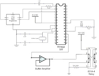

This circuit has been tested with an LED and a solar igniter at the output of the relay and works with both. The code used for the Atmega 328 is posted below.
/*
Balloon Exploder
Standby: Repeatedly blinks an LED
Recieves voltage at input, turns off standby
Waits 5 seconds, then sends a HIGH out to 12 and 13(LED)
*/
void setup() {
// initialize the digital pin as an output.
// Pin 13 has an LED connected
pinMode(13, OUTPUT); //pin 13 is set to an output
pinMode(8, INPUT); //pin 8 is set to an input
pinMode(12, OUTPUT); //pin 12 is set to output
digitalWrite(12,LOW); //pin 12 is initialized as low
}
void loop(){
while(digitalRead(8)==LOW){ // while loop reads pin 8 and will stay in loop until pin 8 recieves 5 volts
digitalWrite(13, HIGH); //writes pin 13 to 5 volts
delay(1000); //waits a second
digitalWrite(13, LOW); //writes pin 13 to 0 volts
delay(1000); //watis a seconds
}
delay(5000); // delays 5 seconds
digitalWrite(13, HIGH); //sets pin 13 to 5 volts
digitalWrite(12, HIGH); //sets pin 12 to 5 volts for transistor
while(1==1); //stays in this state until reset
}
Sunday, 23 October 2011
Schematic for the Blink Program for the Atmega 328
This is the schematic I used to operate the Atmega328 running programs written with the Arduino IDE. The FTDI Basic programmer plugs into the computer via usb cable. I first programmed the chip with the simple blink program.
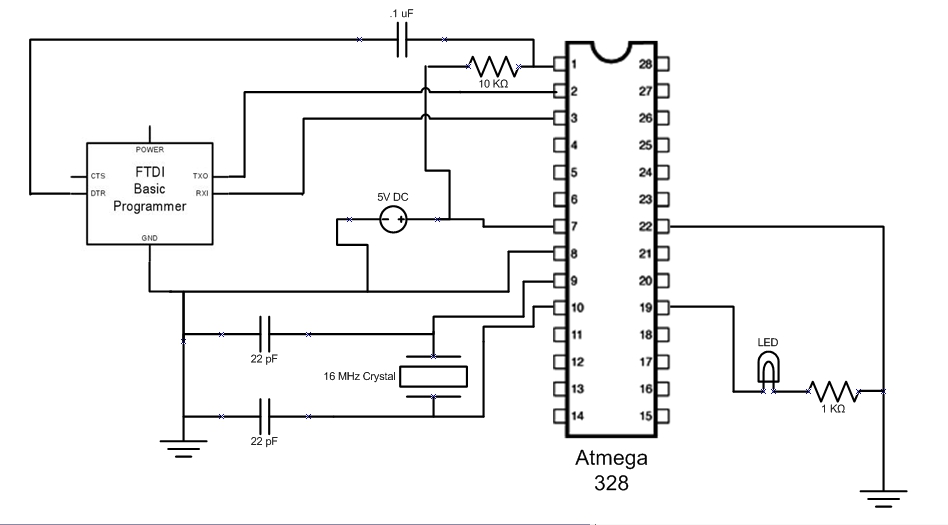
I used the code from the following link http://www.arduino.cc/en/Tutorial/Blink .
The next goal will be to modify the circuit and the programming to receive a digital input, wait a certain amount of time, then send 5 volts to an output. This will be used to pop the balloon when testing the parachute.
Subscribe to:
Posts (Atom)