Thursday, 26 April 2012

Some Pictures of the Flight

Here are some pictures of our last flight. We launched out of Strathmore, Alberta on April 24, 2012.  The first few pictures are before the bursting point of our balloon. The conditions of the day of launch were extremely cloudy. The camera used is a GoPro Hero II.


The first picture after burst. 

During descent just above the clouds. 

Geiger Counter

Updated Geiger Counter Code. This program uses a loop to determine the length of the pulse. Then it will , add one to the value of a counter if the pulse is of a certain length, then waits for another pulse. This program will then write the value to the corresponding place in the memory of the EEPROM chip. The program is designed to change the slots in memory that are being used if a significant change in pressure is detected. In event of pressure change, it will shift the store bits so that the former data remains and new data can be taken at a different altitude. Finally, in the 0th slot of eeprom memory the number of pressure bins is stored, to ensure that the correct amount of data is printed in the print data routine. This design is  to be used to measure the background radiation vs altitude.


/******************************************
Geiger counter Program
Waits for a switch d8 or d9
d8 it is high, then goes into write mode,
counting pulses of specific length
d9 is high, goes into read mode, reading off of EEPROM on atmega
*******************************************/
#include  "Wire.h"    // for External EEPROM CHIP
#define chip 0x50

int a0=0; int b0=0; int c0=0; int d0=0; int e0=0;
int a1=0; int b1=0; int c1=0; int d1=0; int e1=0;
int a2=0; int b2=0; int c2=0; int d2=0; int e2=0;
int a3=0;

int x=0;
void writeEEPROM(int input,int x){
         byte first = lowByte(input);
         byte last = highByte(input);
         writeData(31+x, first);
         writeData(32+x, last);

}
void initializeSlots(int x){
  writeData(32+x,0); writeData(1+x,0); writeData(2+x,0); writeData(3+x,0); writeData(4+x,0); writeData(5+x,0);
  writeData(6+x,0); writeData(7+x,0); writeData(8+x,0); writeData(9+x,0); writeData(10+x,0); writeData(11+x,0);
  writeData(12+x,0); writeData(13+x,0); writeData(14+x,0); writeData(15+x,0); writeData(16+x,0); writeData(17+x,0);
  writeData(18+x,0); writeData(19+x,0); writeData(20+x,0); writeData(21+x,0); writeData(22+x,0); writeData(23+x,0);
  writeData(24+x,0); writeData(25+x,0); writeData(26+x,0); writeData(27+x,0); writeData(28+x,0); writeData(29+x,0);
  writeData(30+x,0); writeData(31+x,0);}
void initializeCounts(){
//reinitializes the counters
    a0=0; b0=0; c0=0; d0=0; e0=0;
    a1=0; b1=0; c1=0; d1=0; e1=0;
    a2=0; b2=0; c2=0; d2=0; e2=0;
    a3=0;
}

void setup(){
  Serial.begin(9600); // for screen output
  Wire.begin();   // wake up, EEPROM
  pinMode(8, INPUT);
  pinMode(9,INPUT);
  pinMode(10,INPUT);
  pinMode(13, OUTPUT);
  pinMode(11,INPUT);
}
void writeData(unsigned int add, byte data)
// writes a byte of data 'data' to the chip at I2C address 'device', in memory location 'add'
{
Wire.beginTransmission(chip);
Wire.write((int)(add >> 8));   // left-part of pointer address
Wire.write((int)(add & 0xFF)); // and the right
Wire.write(data);
Wire.endTransmission();
//Serial.println(data, DEC);
delay(10);
}
byte readData(unsigned int add) // reads a byte of data from memory location 'add' in chip at I2C address 'device'
{
byte result;  // returned value
Wire.beginTransmission(chip); //  these three lines set the pointer position in the EEPROM
Wire.write((int)(add >> 8));   // left-part of pointer address
Wire.write((int)(add & 0xFF)); // and the right
Wire.endTransmission();
Wire.requestFrom(chip,1); // now get the byte of data...
result = Wire.read();  return result; // and return it as a result of the function readData
}
void loop(){
  Serial.println("Waiting For Switch");
  while(digitalRead(8)==LOW && digitalRead(9)==LOW){
    digitalWrite(13, HIGH);
    delay(1000);
    digitalWrite(13,LOW);
    delay(1000);
  }
 
  if(digitalRead(8)==HIGH){
    Serial.println("Initializing Counts");
    initializeCounts();  
    initializeSlots(0);


    Serial.println("Counting Background Radiation");
    int formerMax=900;
    int loopStopper = 1;
    while(digitalRead(8)==HIGH){
    int height = analogRead(0);
    //Serial.println(formerMax);
    //Serial.println(height);
   
    if(height<1000&&height>=900&&formerMax!=1000){
    formerMax=1000;
    x=x+32;
    loopStopper++;
    initializeSlots(x);
    initializeCounts();
    writeEEPROM(formerMax,x);
    }
    else if(height<900&&height>=800&&formerMax!=900){
    formerMax=900;
    x=x+32;
    loopStopper++;
    initializeSlots(x);
    initializeCounts();
    writeEEPROM(formerMax,x);
    }
    else if(height<800&&height>=700&&formerMax!=800){
    formerMax=800;
    x=x+32;
    loopStopper++;
    initializeSlots(x);
    initializeCounts();
    writeEEPROM(formerMax,x);
    }
    else if(height<700&&height>=600&&formerMax!=700){
    formerMax=700;
    loopStopper++;
    x=x+32;
    initializeSlots(x);
    initializeCounts();
    writeEEPROM(formerMax,x);
    }
    else if(height<600&&height>=500&&formerMax!=600){
    formerMax=600;
    x=x+32;
    loopStopper++;
    initializeSlots(x);
    initializeCounts();
    writeEEPROM(formerMax,x);
    }
    else if(height<500&&height>=400&&formerMax!=500){
    formerMax=500;
    x=x+32;
    loopStopper++;
    initializeSlots(x);
    initializeCounts();
    writeEEPROM(formerMax,x);
    }
    else if(height<400&&height>=300&&formerMax!=400){
    formerMax=400;
    x=x+32;
    loopStopper++;
    initializeSlots(x);
    initializeCounts();
    writeEEPROM(formerMax,x);
    }
    else if(height<300&&height>=200&&formerMax!=300){
    formerMax=300;
    x=x+32;
    loopStopper++;
    initializeSlots(x);
    initializeCounts();
    writeEEPROM(formerMax,x);
    }
    else if(height<200&&height>=100&&formerMax!=200){
    formerMax=200;
    x=x+32;
    loopStopper++;
    initializeSlots(x);
    initializeCounts();
    writeEEPROM(formerMax,x);
    }
    else if(height<100&&height>=0&&formerMax!=100){
    formerMax=100;
    x=x+32;
    loopStopper++;
    initializeSlots(x);
    initializeCounts();
    writeEEPROM(formerMax,x);
    }
    /***
    else if(height<450&&height>=400&&formerMax!=450){
    formerMax=450;
    x=x+32;
    loopStopper++;
    initializeSlots(x);
    initializeCounts();
    }
    else if(height<400&&height>=350&&formerMax!=400){
    formerMax=400;
    x=x+32;
    loopStopper++;
    initializeSlots(x);
    initializeCounts();
    }
    else if(height<350&&height>=300&&formerMax!=350){
    formerMax=350;
    x=x+32;
    loopStopper++;
    initializeSlots(x);
    initializeCounts();
    }
    else if(height<300&&height>=250&&formerMax!=300){
    formerMax=300;
    x=x+32;
    loopStopper++;
    initializeSlots(x);
    initializeCounts();
    }
    else if(height<250&&height>=200&&formerMax!=250){
    formerMax=300;
    x=x+32;
    loopStopper++;
    initializeSlots(x);
    initializeCounts();
    }
    else if(height<200&&height>=150&&formerMax!=200){
    formerMax=200;
    x=x+32;
    loopStopper++;
    initializeSlots(x);
    initializeCounts();
    }
    else if(height<150&&height>=100&&formerMax!=150){
    formerMax=150;
    x=x+32;
    loopStopper++;
    initializeSlots(x);
    initializeCounts();
    }
    else if(height<100&&height>=50&&formerMax!=100){
    formerMax=100;
    x=x+32;
    loopStopper++;
    initializeSlots(x);
    initializeCounts();
    }
    else if(height<50&&height>=0&&formerMax!=50){
    formerMax=50;
    x=x+32;
    loopStopper++;
    initializeSlots(x);
    initializeCounts();
    }
    ***/
   
     
      while(digitalRead(10)==LOW && digitalRead(8)==HIGH);    
      int counter=0;
     
      while(digitalRead(10)==HIGH){
      counter++;
      delayMicroseconds(192);
     
      }
     if(counter==1){//0ms<t<.2ms
       a0++;
       byte first = lowByte(a0);
       byte last = highByte(a0);
       writeData(1+x, first);
       writeData(2+x, last);
     }
     else if(counter==2){//.2ms<t<.4ms
       b0++;
       byte first = lowByte(b0);
       byte last = highByte(b0);
       writeData(3+x, first);
       writeData(4+x, last);
     }
     else if(counter==3){//.4ms<t<.6ms
       c0++;
       byte first = lowByte(c0);
       byte last = highByte(c0);
       writeData(5+x, first);
       writeData(6+x, last);
     }
     else if(counter==4){//.6ms<t<.8ms
       d0++;
       byte first = lowByte(d0);
       byte last = highByte(d0);
       writeData(7+x, first);
       writeData(8+x, last);
     }
     else if(counter==5){//.8ms<t<1.0ms
       e0++;
       byte first = lowByte(e0);
       byte last = highByte(e0);
       writeData(9+x, first);
       writeData(10+x, last);
     }
     else if(counter==6){//1.0ms<t<1.2ms
       a1++;
       byte first = lowByte(a1);
       byte last = highByte(a1);
       writeData(11+x, first);
       writeData(12+x, last);
     }
     else if(counter==7){//1.2ms<t<1.4ms
       b1++;
       byte first = lowByte(b1);
       byte last = highByte(b1);
       writeData(13+x, first);
       writeData(14+x, last);
     }
     else if(counter==8){//1.4ms<t<1.6ms
       c1++;
       byte first = lowByte(c1);
       byte last = highByte(c1);
       writeData(15+x, first);
       writeData(16+x, last);
     }
     else if(counter==9){//1.6ms<t<1.8ms
       d1++;
       byte first = lowByte(d1);
       byte last = highByte(d1);
       writeData(17+x, first);
       writeData(18+x, last);
     }
     else if(counter==10){//1.8ms<t<2.0ms
       e1++;
       byte first = lowByte(e1);
       byte last = highByte(e1);
       writeData(19+x, first);
       writeData(20+x, last);
     }
     else if(counter==11){//2.0ms<t<2.2ms
       a2++;
       byte first = lowByte(a2);
       byte last = highByte(a2);
       writeData(21+x, first);
       writeData(22+x, last);
     }
     else if(counter==12){//2.2ms<t<2.4ms
       b2++;
       byte first = lowByte(b2);
       byte last = highByte(b2);
       writeData(23+x, first);
       writeData(24+x, last);
     }
     else if(counter==13){//2.4ms<t<2.6ms
       c2++;
       byte first = lowByte(c2);
       byte last = highByte(c2);
       writeData(25+x, first);
       writeData(26+x, last);
     }
     else if(counter==14){//2.6ms<t<2.8ms
       d2++;
       byte first = lowByte(d2);
       byte last = highByte(d2);
       writeData(27+x, first);
       writeData(28+x, last);
     }
     else if(counter==15){//2.8ms<t<3.0ms
       e2++;
       byte first = lowByte(e2);
       byte last = highByte(e2);
       writeData(29+x, first);
       writeData(30+x, last);
     }
     /**else if(counter>=16){//t>3.0ms
       a3++;
       byte first = lowByte(a3);
       byte last = highByte(a3);
       writeData(31+x, first);
       writeData(32+x, last);
     }**/
   
    }
    writeData(0,loopStopper);
  }
  if (digitalRead(9)==HIGH&&digitalRead(8)==LOW){  
    Serial.println("Printing Data");
    int z=0;
    int lS = readData(0);
    int zStop = (lS-1)*32;
   
    while(z<=zStop){
    Serial.print("0.0ms<t<0.2ms     ");
    byte temp1=readData(2+z)<<8;
    Serial.println(readData(1+z)+temp1);
 
    Serial.print("0.2ms<t<0.4ms     ");
    byte temp3=readData(4+z)<<8;
    Serial.println(readData(3+z)+temp3);
 
    Serial.print("0.4ms<t<0.6ms     ");
    byte temp5=readData(6+z)<<8;
    Serial.println(readData(5+z)+temp5);
 
    Serial.print("0.6ms<t<0.8ms     ");
    byte temp7=readData(8+z)<<8;
    Serial.println(readData(7+z)+temp7);
   
    Serial.print("0.8ms<t<1.0ms     ");
    byte temp9=readData(10+z)<<8;
    Serial.println(readData(9+z)+temp9);

    Serial.print("1.0ms<t<1.2ms     ");
    byte temp11=readData(12+z)<<8;
    Serial.println(readData(11+z)+temp11);

    Serial.print("1.2ms<t<1.4ms     ");
    byte temp13=readData(14+z)<<8;
    Serial.println(readData(13+z)+temp13);
   
    Serial.print("1.4ms<t<1.6ms     ");
    byte temp15=readData(16+z)<<8;
    Serial.println(readData(15+z)+temp15);
   
    Serial.print("1.6ms<t<1.8ms     ");
    byte temp17=readData(18+z)<<8;
    Serial.println(readData(17+z)+temp17);
   
    Serial.print("1.8ms<t<2.0ms     ");
    byte temp19=readData(20+z)<<8;
    Serial.println(readData(19+z)+temp17);
   
    Serial.print("2.0ms<t<2.2ms     ");
    byte temp21=readData(22+z)<<8;
    Serial.println(readData(21+z)+temp21);
   
    Serial.print("2.2ms<t<2.4ms     ");
    byte temp23=readData(24+z)<<8;
    Serial.println(readData(23+z)+temp23);
   
    Serial.print("2.4ms<t<2.6ms     ");
    byte temp25=readData(26+z)<<8;
    Serial.println(readData(25+z)+temp25);
   
    Serial.print("2.6ms<t<2.8ms     ");
    byte temp27=readData(28+z)<<8;
    Serial.println(readData(27+z)+temp27);
   
    Serial.print("2.8ms<t<3.0ms     ");
    byte temp29=readData(30+z)<<8;
    Serial.println(readData(29+z)+temp29);
   
    Serial.print("pressure bin      ");
    byte temp31=readData(32+z)<<8;
    Serial.println(readData(31+z)+temp31);
   
    z=z+32;
    Serial.println();
    }
    Serial.println("\nFinished Printing Data");
    while(digitalRead(9)==HIGH){
        delay(100);
    }
   
 }
 
}

Monday, 13 February 2012

First Test Launch

On Last Friday Feb 10, we did a test launch. We didn't quite have a working barometer for the flight, but I built and tested one this weekend. For the launch, a solder on the data logger came loose and we didn't end up collecting any data. I worked this weekend to make the board robust and rather than soldering the wire connectors, I had put some wire sockets where we actually screw the battery connections in, and if they come loose, all we need is a screwdriver. Finally I reprogrammed the balloon exploder circuit which overloaded with the delay command and didn't function properly.

Here is the schematic for the new barometer.  The first op-amp and transistor is required to make a constant current source for the nph8100ah pressure transducer. The second op-amp is a differential amplifier which takes the difference in the output, and amplifies the voltage so at atmospheric pressure it puts out about 4 volts.

Lastly, here is the code for the new balloon exploder circuit.


/*
 Balloon Exploder
 Standby: Repeatedly blinks an LED at 1 second intervals
 Recieves voltage at input, turns off standby
 Waits x number of minutes, then sends a HIGH out to 12 and LED Rapid Blinks
 */

void setup() {              
  // initialize the digital pin as an output.
  // Pin 13 has an LED connected
  pinMode(13, OUTPUT);    //pin 13 is set to an output
  pinMode(8, INPUT);      //pin 8 is set to an input
  pinMode(12, OUTPUT);    //pin 12 is set to output
  digitalWrite(12,LOW);   //pin 12 is initialized as low
}
void delayMinute()
// delays for a minute
{
  int counter = 0;
  while(counter<60){
    delay(1000);
    counter++;
  }
}
void delayXMinutes(int x){ //delays for x amount of minutes
  int counter = 0;
  while(counter<x){
    delayMinute();
    counter++;
  }
}
void loop(){
  while(digitalRead(8)==LOW){   // while loop reads pin 8 and will stay in loop until pin 8 recieves 5 volts
    digitalWrite(13, HIGH);
    delay(1000);            
    digitalWrite(13, LOW);     //slow blink to show that the switch has not been flipped yet
    delay(1000);            
  }                        
  delayXMinutes(5);               // delays x number of minutes LIGHT IS OFF WHILE waiting
  digitalWrite(12, HIGH);    //sets pin 12 to 5 volts for transistor
  while(digitalRead(8)==HIGH){ //stays in this state until switch is flipped again
    digitalWrite(13, HIGH);
    delay(100);            
    digitalWrite(13, LOW);   //fast blink to show that the fuse has gone off
    delay(100);            
  }            
}

Monday, 30 January 2012

Some Pictures of the circuits

I have taken some pictures of what we have done. Below is a picture of the balloon exploder circuit that will be on the first test launch. Its primary purpose is to wait a designated amount of time, the set off a solar ignitor that will not in fact pop any balloons, but it will burn through the line connecting the parachute and the balloon. 
Below is the data logger I have created. On board is the atmega 328, a 12 volt and 5 volt voltage regulator, a 12v one sided op-amp, usb break out board, dual axis accelerometer, a thermistor, and a barometer. 

Below is the trackuino. This is designed to get the gps signal and send it over the aprs network. It can also transmit temperature and other data aswell. More about it at http://code.google.com/p/trackuino/

This is a photo from inside the Styrofoam box. I had taped down some wires on the balloon exploder circuit (on the top) since I only used a protoboard because this is temporary and only intended for the test flight. We have the data logger on the right and on the left a gps tracker. The trackuino has not yet been tested, although once its working the other gps tracker will probably remain for redundancy.

Here is a shot at another angle. As you can see we have dowel glued in to hold the circuits and other pieces into place while in flight.

Here's a picture of the closed box. We have the radio transmitter sticking out the top and also the wires for the balloon exploder circuit. 

 And another picture of the payload. The total measured weight is 960 grams.

Monday, 23 January 2012

Some Test Data

For the last couple of weeks I have been doing some fine tuning and some testing. First of all, I have been testing the data logger and and now have some calibration data for the barometer and the accelerometer. I have also found out that the thermistor we currently have outputs a negative voltage for negative numbers and a positive voltage for positive numbers. The arduino does not recognize negative voltages. We could have run the thermistor through an opamp to shift the voltage, but since I'm running out of room on my board, it is just easier to order a different one that does only positive voltage. Once this comes in, I will put some test data of the temperature up. I have also done some testing of the balloon exploder circuit. We plan to have a few smaller balloons for the first test flight. It will be easier to cut the line than to have a number of balloon exploders, so I needed to test to see if the solar ignitors will burn through the nylon line. I did a test with simply a solar ignitor connected to 18v and another test with the whole exploder circuit and both tests were successful.

The barometer calibration data is at the following link:
https://docs.google.com/spreadsheet/ccc?key=0AqH-Vyu_xTSKdGFBam9sbFFIbEJUMDRRRER1RG8tcnc
And some test data is at the following link:
https://docs.google.com/spreadsheet/ccc?key=0AqH-Vyu_xTSKdDN1S0EyOVJXRlZWdThxamR1NWpxUEE

Friday, 25 November 2011

FINAL CIRCUIT DESIGN AND CURRENT MEASUREMENTS OF DATA LOGGING CIRCUIT

I have finished designing the data logger. I also measured the current draw of the main components of this circuit.

Arduino                                         47mA
Lm324 (Quad Op-amp)               1.5mA
Lm35 (Thermistor)                        15mA
24L256 (EEPROM)                     33mA
Mx210A (accelerometer)                3mA
MPX100 (barometer)                   10mA

TOTAL                                   ~ 110mA

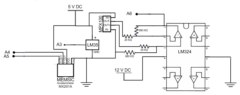
The circuit design is as follows and the code remains the same as it was in the last post.


Note: there is supposed to be a logic switch on pin 14 and pin 15 of the arduino which tell the arduino whether to begin writing data or to read data (this process is in the code)

Saturday, 19 November 2011

Read/Write Program and circuit with External EEPROM Memory Chip

I have created a program and circuit that allows for the reading and writing of memory onto the EEPROM chip. The program has 4 analog inputs, and if the switch at d8 is flipped to 5V, then the microchip will begin to read values from four analog inputs (A6, A5, A4, A3) and write them to the memory of the external EEPROM chip. If the switch at d9 is turned to 5V, then the microchip will existing data from the EEPROM memory chip.


Heres the code I wrote for the program.

/*
WRITE READ 4 ANALOG INPUTS
program waits in a loop for the switch on either d8 or d9 to be thrown.
if d8 is thrown, it goes into write mode writing the voltages at 4 analog inputs
if d9 is thrown, it goes into read mode, reading all the information stored on the eeprom chip (waits for d9 to be shut off)
*/
#include  "Wire.h"    // for External EEPROM CHIP
#define chip 0x50    // device address for our chip
byte d=0; // example variable to handle data going in and out of EERPROM
int endLoop=0; //to define the end of our write loop
void setup()
{
Serial.begin(9600); // for screen output
Wire.begin();   // wake up, EEPROM
}
void writeData(unsigned int add, byte data)
// writes a byte of data 'data' to the chip at I2C address 'device', in memory location 'add'
{
Wire.beginTransmission(chip);
Wire.send((int)(add >> 8));   // left-part of pointer address
Wire.send((int)(add & 0xFF)); // and the right
Wire.send(data);
Wire.endTransmission();
Serial.println(data, DEC);
delay(10);
}
byte readData(unsigned int add) // reads a byte of data from memory location 'add' in chip at I2C address 'device'
{
byte result;  // returned value
Wire.beginTransmission(chip); //  these three lines set the pointer position in the EEPROM
Wire.send((int)(add >> 8));   // left-part of pointer address
Wire.send((int)(add & 0xFF)); // and the right
Wire.endTransmission();
Wire.requestFrom(chip,1); // now get the byte of data...
result = Wire.receive();  return result; // and return it as a result of the function readData
}
void loop()  {
  
  int sensor0=0; // integer value between 0 and 1023 (10 bits) for sensor 1
  int sensor1=0; 
  int sensor2=0;
  int sensor3=0;  
  Serial.println("Waiting to write or read data....");
  while(digitalRead(8)==LOW&&digitalRead(9)==LOW){   // while loop reads pin 8 and will stay in loop until pin 8 recieves 5 volts
    digitalWrite(13, HIGH);  //writes pin 13 to 5 volts
    delay(1000);             //waits a second
    digitalWrite(13, LOW);   //writes pin 13 to 0 volts
    delay(1000);             //watis a seconds
  }
    
  if(digitalRead(8)==HIGH){           //Loop that writes data
    int a=0;
    Serial.println("Writing data...");
    while(digitalRead(8)==HIGH)
    {
      digitalWrite(13, HIGH);  //writes pin 13 to 5 volts
      sensor0=analogRead(A0);
      sensor1=analogRead(A1);
      sensor2=analogRead(A2);
      sensor3=analogRead(A3);
      byte first0  = lowByte(sensor0); //takes the lowest 8 bits from the 10 bit number 
      byte second0 = highByte(sensor0);//takes the takes the last 2 digits from the 10 bit number, and 6 zeros
      byte first1  = lowByte(sensor1); //takes the lowest 8 bits from the 10 bit number 
      byte second1 = highByte(sensor1);//takes the takes the last 2 digits from the 10 bit number, and 6 zeros
      byte first2  = lowByte(sensor2); //takes the lowest 8 bits from the 10 bit number 
      byte second2 = highByte(sensor2);//takes the takes the last 2 digits from the 10 bit number, and 6 zeros
      byte first3  = lowByte(sensor3); //takes the lowest 8 bits from the 10 bit number 
      byte second3 = highByte(sensor3);//takes the takes the last 2 digits from the 10 bit number, and 6 zeros
      writeData(a,first0);
      writeData(a+1,second0);
      writeData(a+2,first1);
      writeData(a+3,second1);
      writeData(a+4,first2);
      writeData(a+5,second2);
      writeData(a+6,first3);
      writeData(a+7,second3);
      delay(5000);
      a=a+8;
    }
    endLoop=a;  
}
  if(digitalRead(9)==HIGH){                ///loop that reads data
    digitalWrite(13,LOW);
    Serial.println("S0   S1   S2   S3");
    int b=0;
    while(b<endLoop)
    {
      byte low0 = readData(b);    //defines low0 as whats in the chips memory space b
      byte high0 = readData(b+1);
      byte low1 = readData(b+2);
      byte high1 = readData(b+3);
      byte low2 = readData(b+4);
      byte high2 = readData(b+5);
      byte low3 = readData(b+6);
      byte high3 = readData(b+7);
      int result0=high0<<8; // rotate left 8 bits the high value and store in result
      int result1=high1<<8;
      int result2=high2<<8;
      int result3=high3<<8;
      Serial.print(result0+low0,DEC);//prints first result 
      Serial.print("  ");
      Serial.print(result1+low1,DEC);//prints second result 
      Serial.print("  ");//puts a space between results
      Serial.print(result2+low2,DEC);//prints third result 
      Serial.print("  ");
      Serial.println(result3+low3,DEC); //prints the fourth result and carridge returns
      b=b+8;
  }
  while(digitalRead(9)==HIGH){}
 } 
}

Wednesday, 9 November 2011

Esitmating the battery life of the components for the test flight

The current draw was measured from the baloon exploder microchip, the gps, and, the buffer op amp, and the data aquisition arduino. The baloon exploder microchip draws about 22 mA while counting, the buffer draws 36 mA (used an lf411 to estimate, but this is a +/- 15V op-amp which we will be replacing with a one sided 12V one that will draw less), the data aquisition microchip draws 25 mA, and the gps draws 45 mA. We are missing current draw from a few 12V regulators, but these aren't in yet, but the draw should be rather low. The current draw from the actual fuze itself is negligible because it will only draw current for less than a second. This gave us an estimated total of 128 mA draw from the entire circuit.

We are planning to use two 9V batteries in series to make 18V which we can regulate down. These batteries have a capacity of 500mAh, giving us an estimated 3.9 hours. These batteries have an operating range of -20°C to 54°C. This should be more than enough for the test flight.

Friday, 4 November 2011

EEPROM MEMORY STORAGE

I have been working on a program that will take data, and store it. Regularly when values are taken from a microchip, the data is stored into SRAM, which is cleared when the power is reset. For our balloon we want to be able to measure voltages from thermistors, pressure sensors and possibly other devices, and we don't want to lose this data when the power is shut off. So this data must be stored to either the EEPROM memory or the Atmega's flash memory. The difference between the two is that data going into EEPROM can only be stored byte by byte, and must be addressed where it is going, where data in flash memory can be stored in tables and arrays and are just stored "somewhere". After struggling with storing and retrieving data from flash memory, I decided to try using the EEPROM, even though we will likely have to use flash memory due to the lack of space in the Atmega's EEPROM.


***UPDATE*** The EEPROM memory will have to be used because only compiled information can be stored in the flash memory. Anything being declared after complile stages cannot be stored in the flash memory. We have placed and order for a seperate EEPROM memory chip that has 128 kB of memory, which will be more than enough for storing the flight data.


Below, is the code I successfully wrote for this process. I will be attempting to learn and figure out how to properly store and retrieve data into the flash memory.


/*
 Analog Reader
 Standby: Repeatedly blinks an LED
 Recieves voltage at input 8, turns off standby
 Repeatedly reads Voltages from analog pin 0, stores them in EEPROM memory.
 Once switch is turned, stops storing and goes into stanby 2 waiting for an input a pin9
 Once this is turned, it will read values either until it has read them all, or pin9 is turned off
*/
#include <EEPROM.h>
void setup() {              
  pinMode(8, INPUT);      //pin 8 is set to an input
  pinMode(13, OUTPUT);    //pin 12 is set to output
  pinMode(9,INPUT);       //pin 9 is set to an input
  Serial.begin(9600);     // baud rate for the chip is set to 9600
  }
void loop(){
  int sensor0 = 0;            //int to store value read from A0
 
  while(digitalRead(8)==LOW){   // while loop reads pin 8 and will stay in loop until pin 8 recieves 5 volts
    digitalWrite(13, HIGH);  //writes pin 13 to 5 volts
    delay(1000);             //waits a second
    digitalWrite(13, LOW);   //writes pin 13 to 0 volts
    delay(1000);             //watis a seconds
  }

  digitalWrite(13,HIGH);
  int k=0;
  while(digitalRead(8)==HIGH){      //while loop stores data in the first 6 bits availiable in EEPROM just for testing purposes
    sensor0=analogRead(A0);         //sets sensor0 to the value read from A0
    byte first  = lowByte(sensor0); //takes the lowest 8 bits from the 10 bit number
    byte second = highByte(sensor0);//takes the takes the last 2 digits from the 10 bit number, and 6 zeros
    int first8bits = first;         //converts the first 8 bits to an int
    int last8bits = second;         //converts the last bits to an int
    EEPROM.write(k, first8bits);    //writes this integer to EEPROM memory in space k
    EEPROM.write((k+1), last8bits); //writes this integer to EEPROM memory in space K+1
    digitalWrite(13,LOW);           //blinks to show it has written
    delay(500);
    digitalWrite(13,HIGH);      
    delay(5000);              
    k=k+2;                          //sets counter variable k=k+2
  }
  while(digitalRead(8)==LOW&&digitalRead(9)==LOW){  ///standby 2. Waits for switch at input9 to be turned on.
    digitalWrite(13,LOW);
    delay(100);
    digitalWrite(13,HIGH);
    delay(100);
  }
  int j=0;                            //new counter variable
  while(j<=k&&digitalRead(9)==HIGH){  //loops until j is i greater than k or switch is turned off
   digitalWrite(13,LOW);              //blink to show what state it is in
   int test1 = EEPROM.read(j);        //sets temp1 variable equal to what is in EEPROM slot j
   int test2 = EEPROM.read(j+1);      //sets temp2 variable equal to what is in eeprom slot j+1
   Serial.println(test1);             //sends numbers to computer via serial
   Serial.println(test2);
   delay(500);
   digitalWrite(13,HIGH);
   j=j+2;                             //counter is increased by 2
  }
}

Thursday, 27 October 2011

Future Plans

I am going to start work on a program that will log data from the analog inputs on the Atmegea 328. This will be used to log the data from a thermistor and a pressure meter that will be on board the flights. We want to be able to store this data on the Arduino, then retrieve after the flight. I will start by attempting to store data from 3 different analog voltages, then retrieve the data afterwords.

Wednesday, 26 October 2011

Exploder Circuit

I am creating a circuit and program to receive a signal from a switch, wait a certain amount of time, then send a voltage out. This will be used to explode a balloon after some time to test the parachute. The signal will leave the Atmega 328 and go though a buffer operational amplifier, and into a relay which is connected to a solar igniter. The buffer is to separate the Atmega from relay and the solar igniter. The chip will not supply enough current to ignite the igniter, so a relay must be used.  The relay will supply current required to the solar igniter that will be attached to the balloon. Originally,a transistor was going to be used, but it leaked current and led to our igniter bursting before it was supposed to. The circuit was modified to contain a mechanical relay which worked, but the current draw through the mechanical relay was about 80 mA, which is high enough for concern (considering this is to be supplied by batteries while in flight). The final version (posted below), uses a solid state relay, which does not have current leakage problems and only draws 9 mA of current.
This circuit has been tested with an LED and a solar igniter at the output of the relay and works with both. The code used for the Atmega 328 is posted below. 


/*
 Balloon Exploder
 Standby: Repeatedly blinks an LED
 Recieves voltage at input, turns off standby
 Waits 5 seconds, then sends a HIGH out to 12 and 13(LED)
*/

void setup() {                
  // initialize the digital pin as an output.
  // Pin 13 has an LED connected
  pinMode(13, OUTPUT);    //pin 13 is set to an output
  pinMode(8, INPUT);      //pin 8 is set to an input
  pinMode(12, OUTPUT);    //pin 12 is set to output
  digitalWrite(12,LOW);   //pin 12 is initialized as low
}
void loop(){
  while(digitalRead(8)==LOW){   // while loop reads pin 8 and will stay in loop until pin 8 recieves 5 volts
    digitalWrite(13, HIGH);  //writes pin 13 to 5 volts
    delay(1000);             //waits a second
    digitalWrite(13, LOW);   //writes pin 13 to 0 volts
    delay(1000);             //watis a seconds
  }                          
  delay(5000);               // delays 5 seconds
  digitalWrite(13, HIGH);    //sets pin 13 to 5 volts
  digitalWrite(12, HIGH);    //sets pin 12 to 5 volts for transistor
  while(1==1);               //stays in this state until reset
}


Sunday, 23 October 2011

Schematic for the Blink Program for the Atmega 328

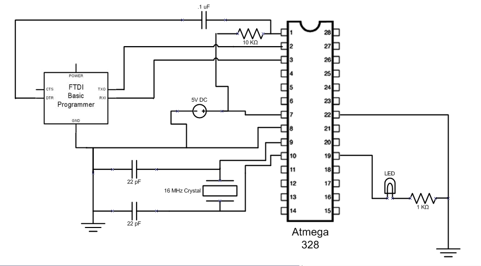
This is the schematic I used to operate the Atmega328 running programs written with the Arduino IDE. The FTDI Basic programmer plugs into the computer via usb cable. I first programmed the chip with the simple blink program.

I used the code from the following link http://www.arduino.cc/en/Tutorial/Blink .

The next goal will be to modify the circuit and the programming to receive a digital input, wait a certain amount of time, then send 5 volts to an output. This will be used to pop the balloon when testing the parachute.